
products
We design and build any part for any system
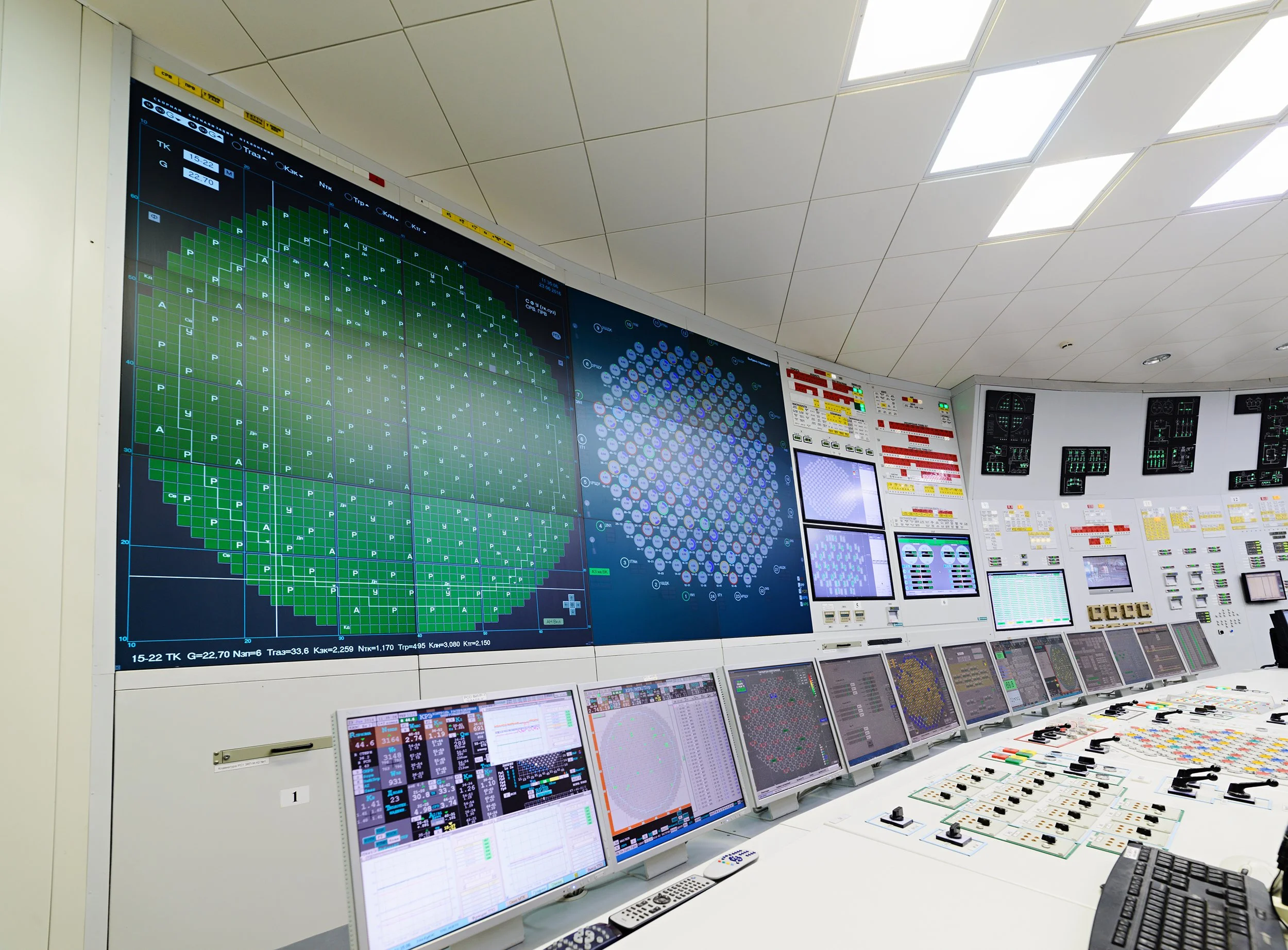
Our team specializes in the design and manufacturing of custom electro-mechanical systems for critical safety instrumentation, with extensive experience supporting nuclear power plant operations. We work closely with our customers to develop fully tailored solutions that meet unique technical, regulatory, and operational requirements.
From concept and engineering through precision manufacturing and testing, we deliver highly reliable, purpose-built systems designed to perform in demanding environments where safety, accuracy, and long-term dependability are essential.
20k+
Products in operation
2k+
Custom projects
Control and Monitoring Panels / Cabinetry
We engineer and fabricate control and monitoring panels to meet the highest industry and regulatory standards. Our cabinetry solutions incorporate precision wiring, military-grade components, and durable finishes, with options for seismic qualification, EMI/EMC compliance, and environmental protection. From PLC-based automation systems to complex instrumentation interfaces, each unit undergoes thorough inspection and functional testing to ensure consistent, reliable performance.
Main Control Room Panels for Plant Control
Logic Relay Panels
Secondary Control Panels
Group 2 Control Panels and Common Hardware
Group 2 Safety Cabinets (40 VDC)
Main Control Room Panel Simulator
Safety Shutdown System Cabinets
Plus many more…
Fully Customizable
Signal Processing and Analog Amplifiers
We design and manufacture high-performance signal processing modules and analog amplifiers for safety-critical applications. From reactor instrumentation to environmental monitoring, our solutions deliver precise, low-noise signal conditioning, amplification, and isolation. Each unit is engineered for accuracy, stability, and durability under the most demanding operational and environmental conditions.
In-Core Flux Detector Amplifiers (Safety Shutdown System 1 and 2 (SDS1 and SDS2))
Reactor Trip Switches (SDS-1 and SDS-2)
Shut-Off Rod Drop Logic Modules
Control Absorber Clutch & Clutch Control Modules
Control Absorber Clutch Relays
Reactivity Modules
Ion Chamber Amplifiers and Trip Comparators (SDS-1 and SDS-2)
RRS Ion Chamber Amplifiers
RRS NOP Amplifiers
Trip Test / Alarm Control Buffer Amplifier (SDS-1 and SDS-2)
In-Core / Trip Test / Alarm Control Buffer Amplifier (SDS-2)
Logic Modules and Printed Circuit Boards
Voltage Comparator and Conditioner Trip Unit
Isolation Modules
Dynamic Signal Compensators
Plus many more…
Fully Customizable
Monitoring and Detection Systems
We design and manufacture advanced monitoring and detection systems that deliver accurate, real-time data in mission-critical environments. From radiation and tritium-in-air monitoring to containment leakage detection, our systems are built for precision, reliability, and long-term performance in the most demanding conditions.
Tritium-in-Air Monitoring Systems (Multiple Room Monitoring System)
Stack Monitoring System
Far Area Gamma Monitoring (FAGM)
Containment Box-Up Monitoring System
Dockside Radiation Monitoring System
Portable Tritium Monitors (Models 209L, 309A)
Gross Containment Leakage Monitoring Systems
Conductivity Measurement Systems and Analyzers
Plus many more…
Fully Customizable
Temperature and Pressure Instrumentation
Our temperature and pressure instrumentation portfolio includes RTD and thermocouple transmitters, alarm monitors, temperature and pressure switches, and differential pressure gauges. Designed for high accuracy, long-term stability, and robust performance, these instruments meet stringent industry standards for EMI/EMC compliance, seismic qualification, and environmental resistance. Each unit is calibrated, tested, and qualified to perform in demanding nuclear, defense, and industrial applications.
PSVS Temperature Alarm Monitors (Thermocouple Amplifiers)
Temperature Transmitters for RTDs
RTD Transmitter
Thermocouple Transmitter
Temperature Alarm Monitor (TAM)
Temperature Switches & Controllers
Fully Customizable
Timers, Relays, Power Supplies
From controlling critical shutdown sequences to delivering stable power in harsh conditions, our timers, relays, and power supplies keep your systems running reliably. Built with the same quality and attention to detail as our large-scale control solutions, they’re trusted in mission-critical environments where failure is not an option.
Solid State Timers (including AGASTAT replacements)
Time Delay Relays
Type I, II, III, IV Relay Modules
Custom Power Supplies
Nimbin Power Supply
Rosemount Power Supply
IE Power Power Supplies
Plus many more…
Fully Customizable
Automation and Specialized Equipment
Our expertise includes the design and build of PLC-based automation systems, motor control assemblies, test modules, and electromechanical handling equipment. We specialize in integrating pneumatics, hydraulics, and electronics into cohesive, operator-friendly systems, with capabilities for seismic qualification, EMI/EMC compliance, and industrial safety standards. Each unit is fully tested and documented for consistent, repeatable performance in critical environments.
Failed Fuel Location Systems (DN Monitoring Systems)
PHT LRV Stroke Time Test Modules
EHG Speed Sensor Detect Module
Speed Sensor Replacement
Potentiometers
Start-Up Instrumentation Systems
Computer Simulation Keyboards & Panels
Reactor Power Display Units
Fail Switch Front Panel with Segment Display
Auto Load and Unload Machines for Dosimeter Handling
Plus many more…
Fully Customizable